How LEDs work
The physics, materials and engineering behind every light-emitting diode
Electroluminescence is the emission of light by a material in direct response to an electric current. In an LED, current flows forward through a semiconductor p–n junction: electrons and holes meet in the junction and recombine, and each recombination can release one photon whose energy matches the material's band gap. Unlike a filament, an LED needs no heat to make light.
Every LED is built on the same physics, whether it is the indicator on a phone charger, a 200-watt stadium floodlight or a sub-pixel in a MicroLED TV: inject charge carriers into a junction, let them recombine, and get photons out. The engineering is about making that happen efficiently, at the color you want, and without letting heat ruin the result. This article works through the physics from first principles, then the practical metrics (lumens, efficacy, CCT, CRI, binning) and the electronics (drivers and dimming) that decide whether an LED product is excellent or awful.
The p–n junction
An LED is a p–n junction: a semiconductor crystal with an n-type side rich in free electrons and a p-type side rich in holes, created by doping, for example with silicon and magnesium in gallium nitride. Light is made where the two sides meet, when electrons and holes are pushed together.
A semiconductor's electrical properties can be controlled precisely by adding small amounts of impurity atoms, a process called doping. In LED materials such as gallium nitride, adding silicon donates extra electrons and makes the material n-type (negative carriers). Adding magnesium creates electron vacancies, called holes, that behave like positive charges, making the material p-type.
The depletion region
Where p-type and n-type material meet, electrons and holes diffuse across and cancel out, leaving a thin depletion region with almost no free carriers. Its fixed charged ions create a built-in electric field and a potential barrier, so with no voltage applied the junction is in equilibrium and emits no light.

Where p-type and n-type material meet, electrons near the boundary diffuse into the p side and fill holes, and holes diffuse the other way. This leaves behind a thin zone with almost no free carriers, the depletion region, containing fixed charged ions: negative acceptors on the p side and positive donors on the n side. These ions create a built-in electric field and a potential barrier that stops further diffusion. With no external voltage, the junction sits in equilibrium and emits nothing.
Forward bias and current flow
With the anode positive and the cathode negative, the applied voltage opposes the built-in barrier. Near the forward voltage, typically 1.8–3.6 V for visible LEDs, the barrier collapses and current rises exponentially, which is why LEDs need current control. Reversed, the barrier grows and almost no current flows.
Connect the p side (the anode) to the positive terminal and the n side (the cathode) to the negative terminal, and the applied voltage opposes the built-in barrier. Once the voltage approaches the forward voltage (Vf), the barrier collapses, the depletion region narrows, and electrons and holes flood into the junction. Current then rises exponentially with voltage. That is why LEDs must be current-controlled (see Drivers). Reverse the polarity and the barrier grows, so almost no current flows. Most LEDs tolerate only about 5 V in reverse before breaking down.
Interactive diagram: P–N junction and band gap explorer
Recombination and electroluminescence
When an electron in the conduction band falls into a hole in the valence band, it releases energy. In radiative recombination that energy leaves as a photon of light, which is electroluminescence; in defect-assisted (Shockley–Read–Hall) or Auger recombination it becomes heat. Good LEDs maximize the radiative path.

Inside the junction, an electron in the high-energy conduction band can drop into an empty state, a hole, in the lower-energy valence band. The energy it loses has to go somewhere. There are three main paths:
- Radiative recombination: the energy leaves as a photon. This is the process we want.
- Shockley–Read–Hall (SRH) recombination: the electron falls via a defect or impurity level and the energy becomes heat (lattice vibrations). Crystal quality controls this loss.
- Auger recombination: the energy is handed to a third carrier, which then loses it as heat. Auger loss grows rapidly at high current density and is a main cause of efficiency droop.
Direct and indirect band gaps
In a direct band gap semiconductor such as GaAs or InGaN, an electron can drop straight into a hole and emit a photon. In indirect materials such as silicon, a lattice vibration must also take part, making light emission thousands of times less likely. That is why silicon cannot make efficient LEDs.
A photon carries almost no momentum. In a direct band gap semiconductor (GaAs, InGaN, AlInGaP), the lowest conduction-band state and the highest valence-band state have the same crystal momentum, so an electron can drop straight down and emit light. In an indirect semiconductor (silicon, germanium, silicon carbide, gallium phosphide), the transition also needs a lattice vibration (phonon) to balance momentum. That makes radiative recombination thousands of times less likely. This is why silicon does not make LEDs, and why early SiC LEDs were so dim.
Heterostructures and quantum wells
Modern LEDs stack multiple quantum wells: InGaN layers only 2–3 nm thick between wider-gap GaN barriers, grown atom by atom by MOCVD. The wells trap electrons and holes together so they recombine efficiently, and adjusting their thickness and indium content sets the emission wavelength within a few nanometers.
Modern LEDs are not simple p–n junctions. They use heterostructures: layers of different alloys grown epitaxially, atom by atom, by metal-organic chemical vapor deposition (MOCVD). The light-emitting core is a stack of multiple quantum wells (MQWs). These are layers of narrow-gap material (for example InGaN) only 2–3 nm thick, sandwiched between wider-gap barriers (GaN). Carriers are trapped in the wells, which raises the chance that an electron and hole meet. Fine-tuning well thickness and indium content sets the wavelength to within a few nanometres.
How efficient is an LED?
LED efficiency multiplies several factors: internal quantum efficiency, the share of recombinations that make photons; light extraction efficiency, the share of photons that escape the chip; and their product, external quantum efficiency. Wall-plug efficiency, optical watts out per electrical watt in, exceeds 60% for the best blue LEDs.
Engineers split LED efficiency into several factors:
Light extraction is hard because semiconductors have a high refractive index, about 2.4–2.5 for GaN and 3.5 for GaAs. Only light that hits the surface within a narrow escape cone gets out. For GaN into air the critical angle is only about 24°, and the rest is reflected back by total internal reflection. Engineers use roughened surfaces, patterned sapphire substrates, flip-chip mounting with reflective contacts, and domed silicone encapsulants to extract more than 80% of the light. The best blue LEDs now reach a wall-plug efficiency above 60% at moderate current. An incandescent lamp turns only about 5% of its input into visible light.
InGaN loses efficiency as indium content rises to reach green, and AlInGaP loses efficiency as it approaches yellow. The result is a dip in efficiency between roughly 530 and 590 nm, exactly where the eye is most sensitive. That is why most white LEDs use phosphors instead of mixing red, green and blue chips.
Band gap and wavelength
Each photon carries roughly the band gap energy of the light-emitting layer, so the band gap sets the color. The rule is λ (nm) ≈ 1240 ÷ Eg (eV): a 2.76 eV InGaN layer emits 449 nm blue, and 1.98 eV AlInGaP emits 626 nm red. Real LEDs emit bands 15–30 nm wide.
The energy of each emitted photon is approximately the band gap energy Eg of the active layer. Photon energy and wavelength are linked by Planck's relation E = hc/λ. With E in electron-volts and λ in nanometres, this reduces to a formula worth memorizing:
Real LEDs emit a narrow band rather than one wavelength, typically 15–30 nm wide (full width at half maximum) for visible InGaN and AlInGaP, and wider for infrared. Thermal energy spreads carriers over a range of states. Heat also shrinks the band gap slightly, so an LED's peak wavelength shifts longer as it warms, roughly 0.03–0.1 nm per °C for blue and more for red and amber.
Interactive diagram: the LED spectrum from 200 to 1000 nm
Semiconductor materials and their colors
LED color is set by the semiconductor alloy. Gallium arsenide and AlGaAs emit infrared and deep red, AlInGaP covers red, orange, amber and yellow, InGaN covers violet, blue and green, and AlGaN reaches ultraviolet. Forward voltage rises with band gap, from about 1.2 V for infrared to 3.6 V for blue and more for ultraviolet.
Each LED material family covers a range of band gaps, which engineers tune by changing the alloy composition. Forward voltage rises with band gap because a photon of energy Eg needs at least Eg/q volts. Real Vf is higher because of contact and series resistance and, in nitrides, polarization barriers.
| Material | Band gap (eV) | Wavelength range | Colors | Typical Vf | Notes |
|---|---|---|---|---|---|
| GaAs (gallium arsenide) | 1.42 | 850–940 nm | Infrared | 1.2–1.5 V | First commercial LED (1962); remotes, optocouplers |
| AlGaAs (aluminium gallium arsenide) | 1.42–1.9 (direct) | 640–880 nm | Deep red, IR | 1.5–2.0 V | "Superbright" reds of the 1980s; 660/730/850 nm today |
| GaAsP (gallium arsenide phosphide) | 1.42–2.26 | 580–700 nm | Red, orange, yellow | 1.8–2.2 V | Holonyak's 1962 red; nitrogen doping for yellow (1972) |
| GaP (gallium phosphide) | 2.26 (indirect) | 555–700 nm | Yellow-green, red | 2.0–2.2 V | Classic dim green indicators (GaP:N, 565 nm) |
| AlInGaP (aluminium indium gallium phosphide) | 1.9–2.3 | 560–650 nm | Red, orange, amber, yellow | 1.9–2.5 V | Today's red and amber; brake lights, traffic signals, RGB |
| InGaN (indium gallium nitride) | ~2.3–3.3 (in use) | 365–550 nm | UV-A, violet, blue, cyan, green | 2.7–3.6 V | Blue pump for white LEDs; Nobel Prize 2014 |
| GaN (gallium nitride) | 3.4 | ~360–370 nm | UV-A | 3.2–4.0 V | Barrier and cladding layers; UV-A emitters |
| AlGaN / AlN | 3.4–6.0 | 210–360 nm | UV-B, UV-C | 4–8 V | Germicidal LEDs; low efficiency |
| SiC (silicon carbide) | ~3.0–3.3 (indirect) | ~470 nm (historic) | Blue | 3.0–3.6 V | Round 1907, Losev 1920s, Cree blue 1989; now a substrate |
The chip is grown on a substrate: GaAs for AlInGaP red, and sapphire, silicon carbide or silicon for InGaN. The substrate affects cost, heat flow and light extraction. Sapphire is cheap and transparent but conducts heat poorly. SiC conducts heat well and matches GaN better, but costs more. GaN-on-silicon allows production on large, cheap wafers.
How LEDs make white light
No semiconductor emits white directly, so LEDs mix colors. Over 95% of white LEDs use a blue chip under a yellow phosphor, sometimes with red phosphor for warmer, higher-CRI light. Others use a violet chip with full-spectrum phosphors, or mix separate red, green and blue chips for color-changing light.
No single semiconductor emits white light, which is a broad mixture of wavelengths. LEDs create it in one of three ways, compared below and explained in turn.
| Method | How it works | Typical CRI | Efficacy | Best for |
|---|---|---|---|---|
| Blue + YAG:Ce phosphor | 450 nm blue chip under a yellow garnet phosphor | Ra 70–80 | Highest: 150–230 lm/W | Streetlights, warehouses, offices, budget bulbs |
| Blue + green and red phosphors | Adds a nitride red (CASN) phosphor for warm, high-CRI light | Ra 90–98, R9 50–95 | High: 120–180 lm/W | Homes, retail, hospitality, healthcare |
| Violet pump + full-spectrum phosphors | 405–420 nm chip with a red-green-blue phosphor blend, no blue spike | Ra 95–99 | Moderate: 80–130 lm/W | Museums, galleries, premium homes |
| RGB or RGBW chips | Separate red, green and blue dies mixed in the optics | Ra 20–80 (RGB); 80–90 with a white die | Moderate, limited by the green gap | Color-changing, stage and display lighting |
1. Phosphor conversion (blue + phosphor)
A phosphor-converted LED covers a 445–455 nm blue InGaN chip with silicone containing YAG:Ce phosphor, which absorbs some blue and emits broad yellow; blue plus yellow looks white. Adding nitride red phosphor gives warmer, higher-CRI light, but each converted photon loses energy as heat, costing roughly 20–30% for warm white.
More than 95% of white LEDs are phosphor-converted (pc-LEDs). A 445–455 nm blue InGaN chip is covered with silicone containing phosphor particles. The classic phosphor is YAG:Ce (cerium-doped yttrium aluminium garnet), which absorbs blue and emits a broad yellow band peaking near 550–570 nm. Leftover blue plus yellow looks white. Adding a nitride red phosphor (for example CaAlSiN3:Eu, "CASN") produces warmer CCTs and higher CRI. Narrow-band phosphors such as KSF (K2SiF6:Mn4+) and β-SiAlON green are used in display backlights for saturated color.
The cost is Stokes loss. Every blue photon converted to yellow or red loses the energy difference as heat in the phosphor, roughly 20–30% for warm white. That is why warm-white and high-CRI LEDs are somewhat less efficient than cool-white ones.
2. RGB color mixing
Mixing red, green and blue chips makes white without phosphor losses and allows any color, but green chips are inefficient, each color ages and drifts differently with temperature, and the spiky spectrum renders colors poorly. RGB therefore suits effects, displays and stage lighting rather than general illumination.
Combining separate red, green and blue chips can also make white, with no Stokes loss and full color control. But because of the green gap, green chips are inefficient. Each color also ages and shifts with temperature differently, so the white point drifts unless optical feedback is used. Saturated RGB white also renders colors poorly, with gaps in the spectrum. RGB is ideal for effects, displays and stage lighting, but rarely for general illumination. RGBW and RGBCCT products add phosphor-white chips for good whites (see Multi-color LEDs).
3. Violet or UV pump with full-spectrum phosphors
Full-spectrum LEDs use a 405–420 nm violet chip with red, green and blue phosphors, so there is almost no blue spike and the spectrum closely follows daylight or incandescent light. CRI can exceed 95 and optical brighteners glow naturally, at somewhat higher cost and lower efficacy than blue-pumped LEDs.
Some high-end LEDs use a violet (405–420 nm) chip with red, green and blue phosphors. There is almost no blue spike, so the spectrum follows daylight or incandescent closely. CRI can exceed 95, and fluorescent whitening agents in fabric and paper glow as they do in sunlight. These "full-spectrum" LEDs cost more and are a little less efficient, and they are used in museums, retail and premium residential lighting.
Lumens, watts and efficacy
Watts measure power used; lumens measure visible light produced, weighted by the eye's sensitivity. Efficacy, in lumens per watt, is the key efficiency figure: a 60 W-equivalent LED bulb gives about 800 lumens from 8–9 W. Candela measures intensity in one direction, lux the light falling on a surface.
Watts measure how much power a lamp consumes. They say nothing directly about how much light it makes. Brightness is measured in lumens (lm), the total visible light output (luminous flux), weighted by the eye's sensitivity curve V(λ). One watt of 555 nm green light equals 683 lm, and the same watt of 450 nm blue is only about 26 lm.
| Quantity | Unit | What it tells you |
|---|---|---|
| Luminous flux | lumen (lm) | Total light output in all directions. A "60 W equivalent" bulb gives ~800 lm. |
| Luminous efficacy | lm/W | Light per watt of electricity: the key efficiency metric. |
| Luminous intensity | candela (cd) | Light in a particular direction. Matters for spotlights, indicators and headlamps. |
| Illuminance | lux (lm/m²), footcandle (lm/ft²) | Light landing on a surface. Offices need ~300–500 lux; 1 fc = 10.76 lux. |
| Luminance | cd/m² ("nits") | Brightness of a surface or screen as seen by the eye. |
| Radiant flux | watt (W optical) | Used for UV and IR LEDs, where lumens are meaningless. |
Efficacy of light sources compared
LEDs are the most efficient common light source. Incandescent bulbs give 10–17 lumens per watt, halogens 15–24, compact fluorescents 50–70 and linear fluorescents 80–100, while LED retrofit bulbs reach 80–150 lm/W and the best LED luminaires reach 150–220 lm/W and last 50,000–100,000 hours.
| Source | Efficacy (lm/W) | Typical life (h) |
|---|---|---|
| Incandescent (A19) | 10–17 | 750–2,000 |
| Halogen | 15–24 | 2,000–4,000 |
| Compact fluorescent (CFL) | 50–70 | 8,000–10,000 |
| Linear fluorescent (T8/T5) | 80–100 | 20,000–36,000 |
| Metal halide | 65–115 | 10,000–20,000 |
| High-pressure sodium | 80–140 | ~24,000 |
| LED lamp (retrofit bulb) | 80–150 | 15,000–25,000 |
| LED luminaire (best in class) | 150–220+ | 50,000–100,000 |
The theoretical maximum depends on the spectrum. White light with good color rendering tops out at roughly 250–370 lm/W, so LEDs still have headroom. Use the energy savings calculator to convert old bulb wattages into LED lumens and dollar savings.
Color quality: CCT, CRI and binning
LED color quality has three parts: correlated color temperature, which says how warm or cool the white looks; color rendering, measured by CRI and TM-30, which says how naturally colors appear; and binning, which keeps the color of LEDs from different batches consistent. All three appear on good datasheets.
Correlated color temperature (CCT)
Correlated color temperature, in kelvin, compares white light with a glowing black body: lower values look warmer. A candle is about 1,850 K, an incandescent bulb 2,700 K, noon sunlight 5,000–5,500 K and an overcast sky 6,500 K. ANSI C78.377 defines the standard LED values from 2,200 to 6,500 K.
CCT describes whether white light looks warm (yellowish) or cool (bluish), in kelvin (K). It refers to the temperature of an ideal black-body radiator that glows the same color: a candle is ~1,850 K, an incandescent bulb ~2,700 K, noon sunlight ~5,000–5,500 K and an overcast sky ~6,500 K. Counter-intuitively, lower kelvin means warmer light. ANSI C78.377-2017 defines standard nominal LED CCTs of 2200, 2500, 2700, 3000, 3500, 4000, 4500, 5000, 5700 and 6500 K.
Because LEDs are not black bodies, their color can sit slightly above (greenish) or below (pinkish) the black-body curve. The distance is Duv. Good products keep it within about ±0.006, and many people prefer a slightly negative Duv.
Color rendering index (CRI, Ra)
The color rendering index compares how eight pastel test colors look under a lamp with a reference source of the same CCT, scoring up to 100. Incandescent and halogen score 100, standard LEDs about 80, high-CRI LEDs 90–98 and high-pressure sodium only about 20–25.
CRI measures how naturally a light source renders colors compared with a reference source of the same CCT, on a scale up to 100. The general index Ra is the average score for eight pastel test colors, R1 to R8. Typical values: incandescent and halogen 100, standard LEDs 80, high-CRI LEDs 90–98, high-pressure sodium about 20–25.
Why R9 matters
R9 measures how well a light renders saturated red, and it is left out of the Ra average. Many cheap LEDs lack deep red and can score Ra 82 with R9 near zero, so skin, wood and food look dull. For homes, retail and photography, choose CRI 90 or more and R9 of at least 50.
Ra excludes R9, saturated red, which is exactly what many cheap LEDs render worst because their spectra lack deep red. An LED can score Ra 82 with an R9 near zero, making skin, wood, meat and red fabrics look dull. For homes, retail and photography, look for CRI ≥ 90 and R9 ≥ 50.
TM-30: the modern alternative
IES TM-30 evaluates color rendering with 99 realistic color samples instead of eight pastels. It reports Rf, a fidelity score similar to CRI, and Rg, a gamut score showing whether colors look more or less saturated than under the reference. It is more informative than CRI and increasingly appears on professional datasheets.
IES TM-30 uses 99 color samples and reports Rf (fidelity, like CRI) and Rg (gamut: whether colors look more or less saturated). It is far more informative than CRI and is increasingly listed in professional datasheets. For room-by-room recommendations and spectra, see the CRI and CCT guide.
Interactive diagram: color temperature, LED spectra and color rendering
Spectral power distribution at this color temperature
Binning: why two "identical" LEDs can look different
Manufacturing variation makes LEDs differ slightly in brightness, color and forward voltage, so makers test each one and sort it into bins. Color consistency is measured in MacAdam ellipse steps: 2–3 steps look uniform side by side, while 5–7 steps show visible differences between fixtures in the same room.
Manufacturing variation means LEDs from one wafer differ slightly in brightness, color and forward voltage. Makers test every LED and sort it into bins: flux bins (lumens), chromaticity bins (small areas of the CIE color diagram) and Vf bins. Color consistency is expressed in MacAdam ellipses (SDCM, standard deviation of color matching). A 2- or 3-step MacAdam bin looks uniform side by side, while 5–7 steps can show visible differences between fixtures. Quality fixtures specify 3-step or tighter, which matters most in linear coves and rows of downlights.
| Bin size | Visible difference side by side | Typical use |
|---|---|---|
| 1-step | None: indistinguishable | Color-critical display and museum work; rare and costly |
| 2-step | Barely perceptible, even to trained eyes | Premium architectural fixtures, galleries, long linear runs |
| 3-step | Slight; usually unnoticed | Quality commercial and residential fixtures |
| 4-step | Noticeable on uniform white walls | Mid-range products |
| 5-step | Clearly visible across a row of fixtures | Budget products and many LED strips |
| 7-step | Obvious mismatch | Roughly the size of an ANSI C78.377 nominal-CCT quadrangle |
Thermal management
LEDs convert much of their input power into heat inside a tiny chip, and that heat must flow through the package, circuit board and heat sink. Junction temperature is critical: higher temperatures immediately reduce light output, shift color, speed up aging and shorten driver life, so good thermal design matters.
LEDs do not radiate heat as infrared the way filaments do, but they still turn a large share of their input power into heat inside the chip. Even a 50%-efficient LED dissipates half its input as heat in a die smaller than a grain of rice, and that heat must be conducted away through the package, the circuit board and a heat sink. The critical number is the junction temperature (Tj).
Higher junction temperature causes, in order of urgency:
- Immediate light loss. White InGaN LEDs lose roughly 10–15% of output between 25 °C and 100 °C. AlInGaP red and amber can lose 40% or more.
- Color shift. Phosphor efficiency and peak wavelength change with temperature.
- Faster aging. Lumen depreciation roughly doubles for every 10–20 °C rise, as the phosphor, silicone and package plastics degrade.
- Driver failure. Electrolytic capacitors in the driver age fastest of all and are the most common cause of "dead" LED bulbs.
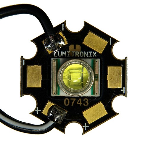
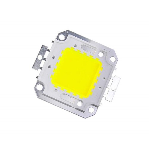
Good thermal design uses metal-core PCBs (aluminium or copper) or ceramic substrates, thermal interface material, and correctly sized heat sinks. Fans are used only where needed, as in compact automotive headlight bulbs. A rule of thumb for passive cooling is about 30–50 cm² of effective heat-sink surface per watt of heat. This is why a cheap bulb in an enclosed fixture can fail early: heat has nowhere to go. See the package cross-sections for how heat leaves DIP, SMD and COB LEDs.


Thermal runaway and junction temperature
An LED's forward voltage drops by about 1.5–4 mV per °C as it heats, so on a fixed voltage a warmer LED draws more current, heats further and can destroy itself within minutes. Constant-current drivers, series resistors, heat sinking and thermal foldback prevent this thermal runaway.
An LED's forward voltage falls as it warms, by roughly 1.5–4 mV per °C for InGaN and AlInGaP chips. On a fixed-voltage supply without current limiting, that creates a positive feedback loop: a warmer LED conducts more current at the same voltage, the extra current makes more heat, and the voltage it needs drops further. Within seconds to minutes the junction overheats and the LED fails, often taking a bond wire or the phosphor with it.
The same effect causes current hogging in parallel strings. The string that runs slightly hotter, or has a slightly lower Vf, draws more than its share, heats further and eventually fails, pushing its current onto the survivors. The defences are a constant-current driver or a series resistor for each string (see Drivers), keeping Tj well below the datasheet maximum (typically 125–150 °C, with 85 °C or lower a sensible design target), and drivers with thermal foldback that reduce the current when a temperature sensor reports overheating.
Drivers: constant current vs. constant voltage
Because LED current rises exponentially with voltage, every LED needs current limiting. Constant-current drivers regulate the current for series strings, COBs and high-power fixtures; constant-voltage supplies of 12, 24 or 48 V power strips with built-in resistors; and a simple series resistor is enough for low-power indicators.
Because LED current rises exponentially with voltage, and Vf falls by about 2 mV/°C as the chip warms, feeding an LED from a fixed voltage invites thermal runaway. More current makes more heat, which lowers Vf, which draws even more current. Every LED therefore needs something that limits current.
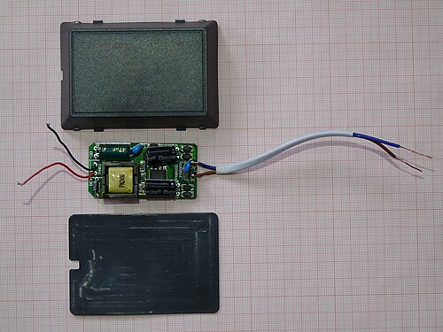

Constant-current (CC) drivers
A constant-current driver holds the current fixed, for example at 350, 700, 1,050 or 1,400 mA, and lets its output voltage float to suit the LED string. These switch-mode drivers reach 85–95% efficiency and power high-power LEDs, COBs, downlights, high-bays and streetlights, usually wired in series.
A constant-current driver regulates the current (for example 350, 700, 1,050 or 1,400 mA) and lets the output voltage float within a window to suit the string's total Vf. CC drivers are standard for high-power LEDs, COBs, downlights, high-bays and streetlights. They use switching topologies (buck, boost or flyback) and reach 85–95% efficiency. LEDs are usually wired in series strings so the same current flows through each one. Paralleling strings without balancing can let one string hog current.
Constant-voltage (CV) drivers
A constant-voltage driver is a regulated 5, 12, 24 or 48 V power supply for products with their own current limiting, mainly LED strips. It makes systems easy to extend and cut, but voltage drop dims long runs, which is why 24 V strips, drawing half the current of 12 V, are preferred.
A constant-voltage driver (a regulated 5, 12, 24 or 48 V power supply) is used with products that carry their own current limiting, most commonly LED strips. They have small resistors or linear constant-current ICs on board. CV systems are simple to extend and cut to length, but voltage drop along long runs causes dimming at the far end. That is why 24 V strips (half the current of 12 V for the same power) are preferred for long runs, with power fed at both ends where needed.
The simple series resistor
For low-power indicator LEDs, a single resistor sets the current using R = (Vsupply − Vf) ÷ If. For example, a 2 V red LED at 20 mA on a 5 V supply needs 150 ohms. It is cheap and reliable at small currents but wastes power and regulates poorly if the supply varies.
For low-power indicators, a single resistor sets the current: R = (Vsupply − Vf) / If. It is cheap and reliable at small currents, but it wastes power and regulates poorly if the supply varies. Try it with the LED resistor calculator, which also picks the nearest standard E24 value and shows the color bands. Driver topologies, ripple and power factor are covered in depth in LED drivers and flicker.
Dimming and flicker
LEDs dim in two ways: constant-current reduction lowers the DC current without flicker, while pulse-width modulation switches the LED fully on and off and varies the duty cycle. PWM keeps color constant and dims precisely, but at a few hundred hertz it can cause flicker; above about 3 kHz it is low risk.
LEDs can be dimmed in two basic ways:
- Analog (constant-current reduction, CCR): the driver lowers the DC current. There is no flicker, but color can shift slightly at very low levels and very deep dimming is hard to control.
- Pulse-width modulation (PWM): the LED is switched fully on and off at a fixed frequency and the duty cycle sets the average brightness. At 25% duty, the LED is on a quarter of the time. Color stays constant and dimming is precise down to 0.1% or less. The cost is potential flicker.
Low-frequency PWM (a few hundred hertz) can cause visible stroboscopic effects, headaches for sensitive people, and banding on camera. The IEEE 1789-2015 recommended practice considers flicker low-risk when modulation is limited at low frequencies and essentially no observable effect above about 3 kHz. Quality drivers use PWM at several kilohertz or higher, or hybrid PWM/CCR. Phone cameras in slow-motion mode reveal flicker easily.
Dimming control protocols
Retrofit LED bulbs use phase-cut wall dimmers, either leading-edge TRIAC or trailing-edge ELV, with mixed compatibility. Commercial fixtures use 0–10 V analog or digital DALI control, smart homes add Zigbee, Thread/Matter or Bluetooth Mesh, and stage and architectural lighting uses DMX512 and its Ethernet versions, Art-Net and sACN.
Retrofit LED bulbs work with legacy phase-cut (TRIAC, leading-edge or trailing-edge ELV) wall dimmers, with mixed results. Check compatibility lists to avoid buzzing, flicker or a limited range. Commercial luminaires use 0–10 V analog control or digital DALI (IEC 62386), and smart homes add Zigbee, Z-Wave, Thread/Matter or Bluetooth Mesh. Stage and architectural lighting uses DMX512 and its Ethernet versions (Art-Net, sACN) to address thousands of channels. Flicker metrics, the IEEE 1789 limits and the EU ecodesign rules are explained in LED drivers and flicker.
Lifetime and reliability
LEDs rarely burn out; they fade. Lifetime is quoted as L70, the hours until output drops to 70% of its initial value, based on IES LM-80 tests of at least 6,000 hours projected with TM-21. Well-cooled luminaires last 50,000–100,000 hours, but hot, cheap bulbs may fail in a few thousand.
LEDs rarely burn out suddenly. They fade. Lifetime is quoted as L70 (or L80/L90): the hours until output falls to 70% (or 80%/90%) of the initial value. Manufacturers test packages for at least 6,000 hours under the IES LM-80 method and project lifetimes with IES TM-21, which limits projections to six times the test duration. That is why ">36,000 h" or ">60,000 h" values are common.
In practice a product's lifetime is set by its weakest part: driver capacitors, solder joints under thermal cycling, yellowing of plastic housings and lenses, or moisture and sulfur corrosion of silver-plated lead frames. A well-cooled LED luminaire from a reputable maker routinely lasts 50,000–100,000 hours, over 11 years of continuous operation. A cheap, hot-running retrofit bulb may last only a few thousand. The test methods, L and B ratings and failure modes are explained in LED lifespan: L70, LM-80 and TM-21.
Frequently asked questions
How does an LED produce light?
Forward current pushes electrons and holes into the p–n junction, where they recombine. Each radiative recombination releases a photon with energy close to the band gap. This is electroluminescence.
What determines LED color?
The semiconductor's band gap: λ (nm) ≈ 1240 / Eg (eV). White LEDs use a blue chip plus phosphor.
Why does an LED need a resistor?
Current rises exponentially with voltage and Vf falls as the LED heats, so without a resistor or constant-current driver the current runs away and destroys the LED.
Do LEDs get hot?
The light beam carries little heat, but 40–70% of the input power becomes heat at the chip, and it must be conducted away. Hot LEDs lose brightness and lifetime.
What CRI should I buy?
CRI 80 is the commercial minimum. Choose CRI 90+ (with R9 above 50) for homes, kitchens, retail and bathrooms, and CRI 95+ for art, photography and color matching.
Is 2700 K or 4000 K better?
2700–3000 K suits living spaces and evening use. 3500–4000 K suits kitchens, offices and garages. 5000 K and above suits workshops and inspection. See the interactive CCT scale above.
Sources and further reading
- E. F. Schubert, Light-Emitting Diodes, 3rd ed. (2018).
- S. M. Sze, K. K. Ng, Physics of Semiconductor Devices, 3rd ed., Wiley (2006).
- CIE 13.3-1995, Method of measuring and specifying colour rendering properties of light sources.
- ANSI C78.377-2017, Specifications for the chromaticity of solid-state lighting products.
- IES TM-30-20, Method for evaluating light source color rendition; IES LM-80-20 and TM-21-21.
- IEEE 1789-2015, Recommended practices for modulating current in high-brightness LEDs for mitigating health risks to viewers.
- U.S. DOE Solid-State Lighting R&D Opportunities reports (2019–2022).
- NEMA SSL 7A-2015, Phase-Cut Dimming for Solid State Lighting: Basic Compatibility; IEC 62386, Digital addressable lighting interface (DALI).
- CIE S 017:2020, ILV: International Lighting Vocabulary, International Commission on Illumination (CIE).
Image credits
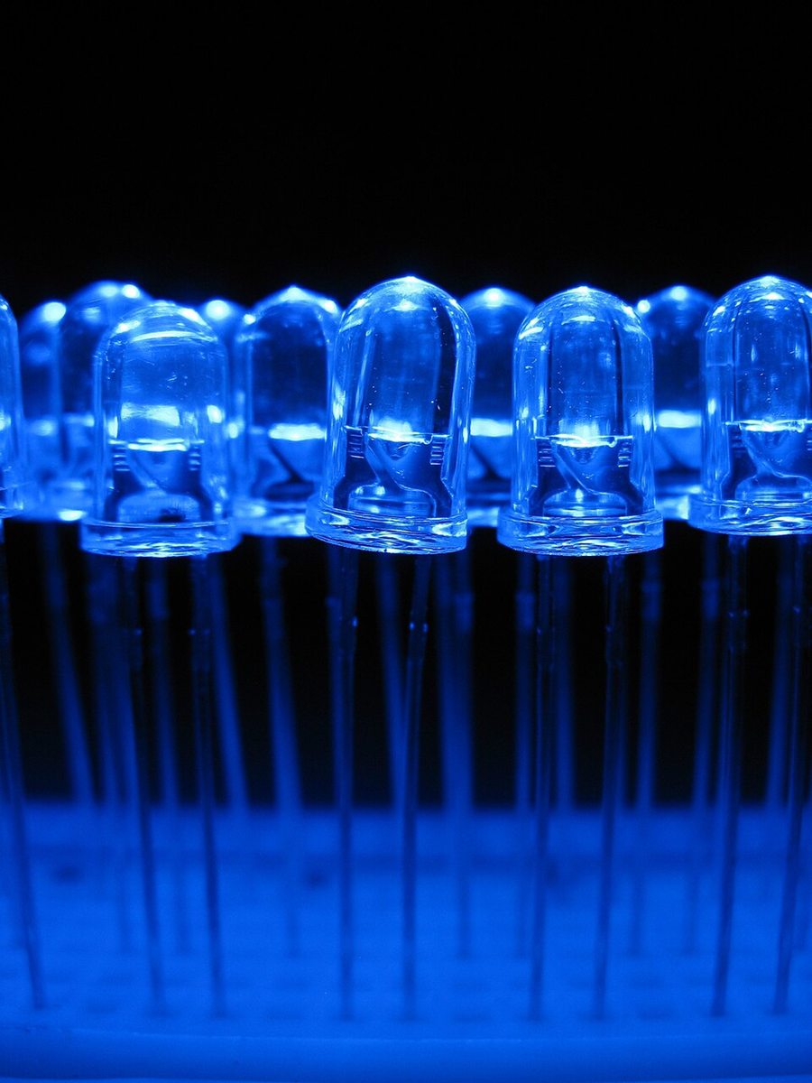
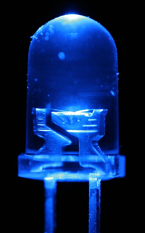
- RGB LEDs: PiccoloNamek, CC BY-SA 3.0. Blue LED macro: outlaw_wolf, CC BY-SA 2.0. Blue LEDs on a breadboard: Gussisaurio, CC BY-SA 3.0. 3 W Cree LED on star board: Kiu77, CC BY-SA 3.0.
- 100 W COB LED: Antonireykern, CC BY-SA 4.0. Constant-current LED driver: Dmitry G, CC BY-SA 4.0. All via Wikimedia Commons. All diagrams: LEDlights.org.